Today, I am going to talk about my reflection about process modelling. During the lecture on week 6 and the workshop, I have finish a number of process modelling diagram, including context diagram, data flow diagram and entity-relationship diagram, each of these three has its meaning and is use for in terms of software model driven development.
Firstly, it is important to explain my understanding about these three diagram:
- Context diagram
Context diagram (also called system context diagram) in software engineering describes the boundary between different systems, some parts of the system or the environment of the system. It illustrates the entities which are involved in. (Choubey, 2012). In other words, it gives an overview about the input, output and participated entity of the system.

Here is an example of system context diagram, the picture is from Data Exploitation website. As can be seen from the diagram, there are seven entities which are related to NDE system, among which IDPS and MMC are two input entities and IPO, CLASS and Management are three output entities. While the entity CUSTOMER and Product Developer combine both input and output.
The system context diagram is the top level view of the system.
- Data flow diagram (DFD)
Data flow diagram represents data as visible flows, to illustrate where the data goes and how they enter the the system, and how the data being processed and outflow the system.
The chart which shows the whole system is one step is level 0 DFD, in this case, we can only see the input and output. However, level 0 DFD could be decomposed, then we get the level 1 and level 2 ...etc as the result. Once the DFD cannot be decomposed, it is in the bottom level.

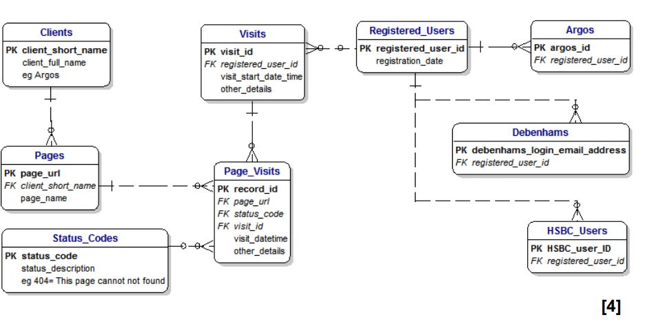
3 Entity-Relationship Diagram (ERD)
In software engineering, an entity-relationship diagram is used to describe the relationship between entities. It is similar to data modelling, but can show the process of the whole system.
Therefore, these three diagrams is process modelling are in progressive relationship. Because the first one shows the system as a whole while the last one shows it in detail.
Secondly, processing has a number of common and unique points compared with data and state modelling:
- Process modelling deals with data and state at the same time, which data modelling and state modelling deal with only data and state respectively.
- Process modelling models the whole system, from start to end, this is called the process, while data modeling and state modelling focus only one part of the system
Therefore, process modelling is based on data and state modelling, which is in a higher level of model-driven development.
In summary, process modelling focuses on the process of the whole system, it includes the change of state and data. However, it is not the highest level of model-driven modelling, because there still has executable model and domain integration, which I am going to talk about later. So, process modelling is acting as a bridge which connects the lower level and the higher level of model-driven methods.
Reference
Manoj Kumar Choubey (2012) IT Infrastructure and Management (For the GBTU and MMTU). p. 53
NDE Project Management (NPOESS) Data Exploitation website. 2008. http://projects.osd.noaa.gov/NDE/proj_context_diagram.htm
没有评论:
发表评论